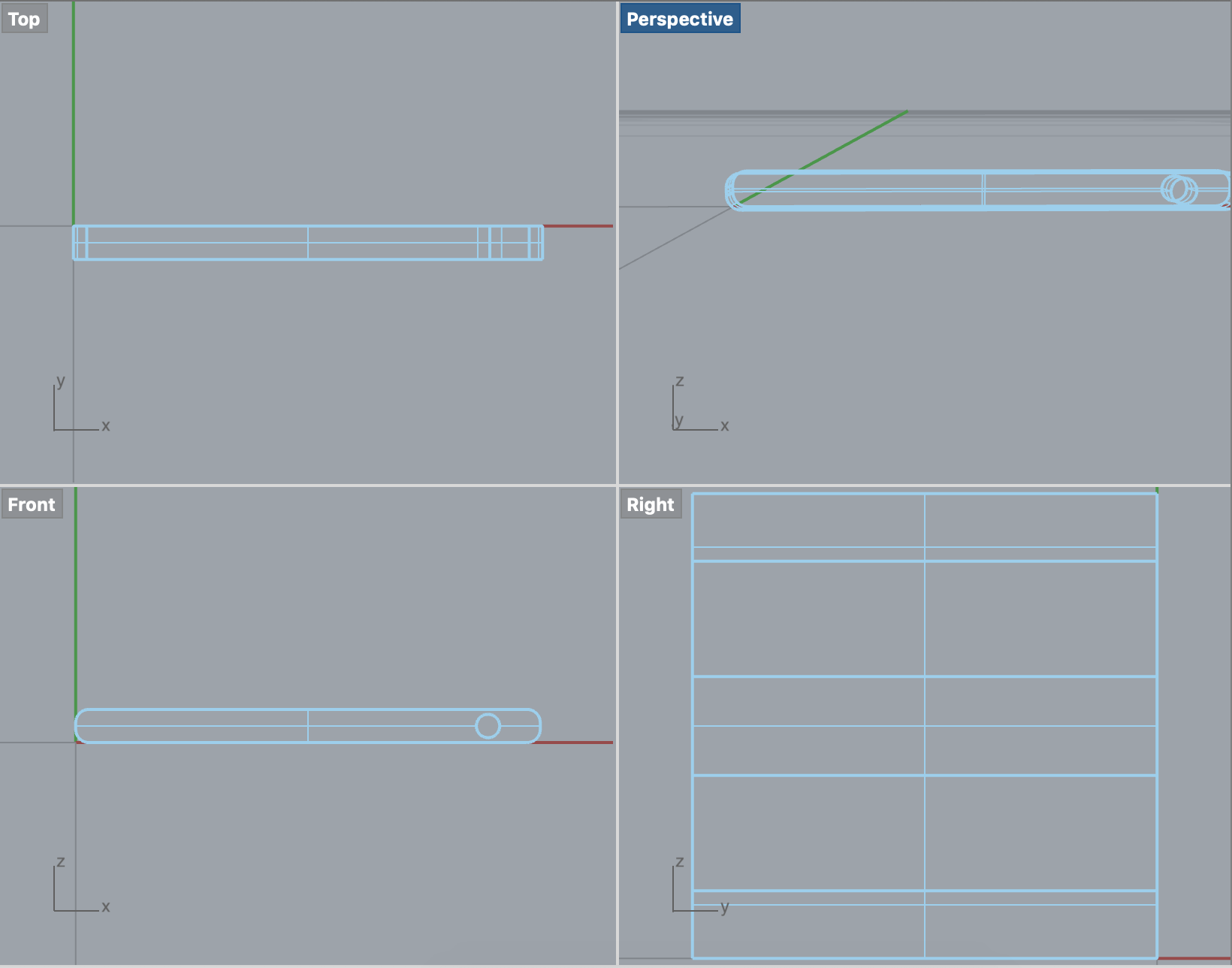
Mate two entities allowing rotational movement about the Z axis and translational movement along the X axis. (Rz, Tx)

This functionality is available on Onshape's browser, iOS, and Android platforms.
8:43 Onshape How to use the pin slot and tangent mate. This video will illustrate how to use the pin slot mate the tangent mate. It will also illustrate how to set limits to a model and how limits work with mate constraints. Uploaded yesterday by Arthur Griffith, Jr. 15:17 Onshape: how to use the Cylindrical and planar mates (without limits). Time limit: 0 Quiz Summary 0 of 5 questions completed Questions: Information You have already completed the quiz before. Hence you can not start it again. Quiz is loading You must sign in or sign up to start the quiz. You must first complete the following: Results Quiz complete. Results are being recorded. Results 0 OnShape 2 Read More ». Onshape lesson 12 How to use the sliderplanar and cylindrical mates.pdf onshape lesson 13 How to use the Pin slot and Tangent mates.pdf onshape lesson 14 How to use the ball and Parallel mate constraints.pdf onshape lesson 15 How to use limits.pdf onshape lesson 16 The anatomy of a gear.pdf.

Mate two entities allowing rotational movement about the Z axis and translational movement along the X axis. (Rz, Tx)

The first Mate connector selected (inferred or existing) serves as the pin and the rotational movement point. The second Mate connector selected (inferred or existing) serves as the translational movement.
Begin by creating Mate connectors on each entity, or use the implicit Mate connectors visible upon hover.
Steps
- Click .
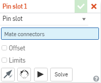
- Select two Mate connectors (inferred or existing), selecting the pin's Mate connector first.
The first Mate connector you select represents the Pin (and the rotational motion of the mate, the pin rotation), the second mate connector represents the Slot (and the translational motion of the mate, the pin moving in the slot).
- To limit the movement, check Limits and supply (optional) minimum and maximum values to control the range of motion of the Mate. Limits are visualized in the graphics area as dashed lines with bars at the ends. The dashed lines represent the direction and distance of the movement and the solid lines represent the limit.
- To supply an offset distance, check Offset and supply a distance. Pin slot Mates can offset the entities only along the Z axis.
Offset distances are visualized in the graphics area as dashed lines between the mates, displaying the value and the axis. Enter the distance in the dialog.
When you click on a Mate, graphics are displayed to indicate the direction of the X, Y, and Z as defined by the Mate along with the offset and the range of limits dimensions (if any).
Applying an offset should be viewed as moving the entire coordinate system. The offset is relative to the Mate connector (inferred or existing) selected first.
You can also select to rotate the part about a specific axis: select the axis, then enter the degrees of rotation.
- Click the entity to access the manipulator.
- Click and drag the various manipulator handles to see which motions are allowed; notice that only rotational movement about the Z axis and translational movement along the X axis is allowed (Rz, Tx).
Steps
- Tap .
- Confirm that Pin slot is selected in the Mate type field.
- Select two Mate connectors (inferred or existing) to use.
The first Mate connector selected (inferred or existing) serves as the pin and the rotational movement point. The second Mate connector selected (inferred or existing) serves as the translational movement.
- Optionally, tap Offset to provide an offset distance.
- Optionally, tap Limits to set distance limits for movement.
- Optionally, tap to Flip the primary axis, Z orientation of the instances.
- Optionally, tap to Reorient the secondary axis; rotate the quadrant orientation (in the XY plane) of the instances by 90 degrees at a tap.
- Tap checkmark.
Touch and drag OR use the Triad Manipulator to move one of the parts. Notice that only rotational movement about the Z axis and translational movement along the X axis is allowed (Rz, Tx).
Pin Slot Mate: AndroidSteps
- Tap .
- Confirm that Pin slot is selected in the Mate type field.
- Select two Mate connectors (inferred or existing) to use.
The first Mate connector selected (inferred or existing) serves as the pin and the rotational movement point. The second Mate connector selected (inferred or existing) serves as the translational movement.
- Optionally, tap Offset to provide an offset distance.
- Optionally, tap Limits to set distance limits for movement.
- Optionally, tap to Flip the primary axis, Z orientation of the instances.
- Optionally, tap to Reorient the secondary axis; rotate the quadrant orientation (in the XY plane) of the instances by 90 degrees at a tap.
- Tap checkmark.
Touch and drag OR use the Triad Manipulator to move one of the parts. Notice that only rotational movement about the Z axis and translational movement along the X axis is allowed (Rz, Tx).
Was this article helpful?
Last Updated: December 10, 2020Mates in Onshape are different from mates in other CAD software. We all use mates in CAD software to create assemblies, so in this post, we will see the various type of Mates available in Onshape.
In Onshape there is just one Mate between any two parts, and therefore the movement (degrees of freedom) between those two parts embedded within the Mate. You only need to use one Mate to define the degrees of freedom between two entities.
Onshape Mate with Zero Degree Freedom
Fastened
This mate limits all degrees of freedom between two parts.
OnshapeMates with One Degree of Freedom
Revolute
This mate allows rotation about the Z-axis.
Slider
This mate allows translation along the Z-axis.
OnshapeMates withTwo Degrees of Freedom

Pin Slot Mate
This mate allows rotation about the Z-axis and translation along the X-axis
Cylindrical Mate
This mate allows translation along the Z-axis and rotation about the Z-axis.
OnshapeMates withThree Degrees of Freedom
Planar Mate
This mate allows translation along the X and Y axes and rotation about the Z-axis.
Ball Mate
This mate allows rotation about all three axes.
OnshapeMate with Four Degrees of Freedom
Pin Slot Mate Onshape
Parallel Mate
This mate allows translation along all three axes and rotation about the Z-axis.

This functionality is available on Onshape's browser, iOS, and Android platforms.
8:43 Onshape How to use the pin slot and tangent mate. This video will illustrate how to use the pin slot mate the tangent mate. It will also illustrate how to set limits to a model and how limits work with mate constraints. Uploaded yesterday by Arthur Griffith, Jr. 15:17 Onshape: how to use the Cylindrical and planar mates (without limits). Time limit: 0 Quiz Summary 0 of 5 questions completed Questions: Information You have already completed the quiz before. Hence you can not start it again. Quiz is loading You must sign in or sign up to start the quiz. You must first complete the following: Results Quiz complete. Results are being recorded. Results 0 OnShape 2 Read More ». Onshape lesson 12 How to use the sliderplanar and cylindrical mates.pdf onshape lesson 13 How to use the Pin slot and Tangent mates.pdf onshape lesson 14 How to use the ball and Parallel mate constraints.pdf onshape lesson 15 How to use limits.pdf onshape lesson 16 The anatomy of a gear.pdf.
Pin Slot Mate: DesktopMate two entities allowing rotational movement about the Z axis and translational movement along the X axis. (Rz, Tx)
The first Mate connector selected (inferred or existing) serves as the pin and the rotational movement point. The second Mate connector selected (inferred or existing) serves as the translational movement.
Begin by creating Mate connectors on each entity, or use the implicit Mate connectors visible upon hover.
Steps
- Click .
- Select two Mate connectors (inferred or existing), selecting the pin's Mate connector first.
The first Mate connector you select represents the Pin (and the rotational motion of the mate, the pin rotation), the second mate connector represents the Slot (and the translational motion of the mate, the pin moving in the slot).
- To limit the movement, check Limits and supply (optional) minimum and maximum values to control the range of motion of the Mate. Limits are visualized in the graphics area as dashed lines with bars at the ends. The dashed lines represent the direction and distance of the movement and the solid lines represent the limit.
- To supply an offset distance, check Offset and supply a distance. Pin slot Mates can offset the entities only along the Z axis.
Offset distances are visualized in the graphics area as dashed lines between the mates, displaying the value and the axis. Enter the distance in the dialog.
When you click on a Mate, graphics are displayed to indicate the direction of the X, Y, and Z as defined by the Mate along with the offset and the range of limits dimensions (if any).
Applying an offset should be viewed as moving the entire coordinate system. The offset is relative to the Mate connector (inferred or existing) selected first.
You can also select to rotate the part about a specific axis: select the axis, then enter the degrees of rotation.
- Click the entity to access the manipulator.
- Click and drag the various manipulator handles to see which motions are allowed; notice that only rotational movement about the Z axis and translational movement along the X axis is allowed (Rz, Tx).
Steps
- Tap .
- Confirm that Pin slot is selected in the Mate type field.
- Select two Mate connectors (inferred or existing) to use.
The first Mate connector selected (inferred or existing) serves as the pin and the rotational movement point. The second Mate connector selected (inferred or existing) serves as the translational movement.
- Optionally, tap Offset to provide an offset distance.
- Optionally, tap Limits to set distance limits for movement.
- Optionally, tap to Flip the primary axis, Z orientation of the instances.
- Optionally, tap to Reorient the secondary axis; rotate the quadrant orientation (in the XY plane) of the instances by 90 degrees at a tap.
- Tap checkmark.
Touch and drag OR use the Triad Manipulator to move one of the parts. Notice that only rotational movement about the Z axis and translational movement along the X axis is allowed (Rz, Tx).
Pin Slot Mate: AndroidSteps
- Tap .
- Confirm that Pin slot is selected in the Mate type field.
- Select two Mate connectors (inferred or existing) to use.
The first Mate connector selected (inferred or existing) serves as the pin and the rotational movement point. The second Mate connector selected (inferred or existing) serves as the translational movement.
- Optionally, tap Offset to provide an offset distance.
- Optionally, tap Limits to set distance limits for movement.
- Optionally, tap to Flip the primary axis, Z orientation of the instances.
- Optionally, tap to Reorient the secondary axis; rotate the quadrant orientation (in the XY plane) of the instances by 90 degrees at a tap.
- Tap checkmark.
Touch and drag OR use the Triad Manipulator to move one of the parts. Notice that only rotational movement about the Z axis and translational movement along the X axis is allowed (Rz, Tx).
Was this article helpful?
Last Updated: December 10, 2020Mates in Onshape are different from mates in other CAD software. We all use mates in CAD software to create assemblies, so in this post, we will see the various type of Mates available in Onshape.
In Onshape there is just one Mate between any two parts, and therefore the movement (degrees of freedom) between those two parts embedded within the Mate. You only need to use one Mate to define the degrees of freedom between two entities.
Onshape Mate with Zero Degree Freedom
Fastened
This mate limits all degrees of freedom between two parts.
OnshapeMates with One Degree of Freedom
Revolute
This mate allows rotation about the Z-axis.
Slider
This mate allows translation along the Z-axis.
OnshapeMates withTwo Degrees of Freedom
Pin Slot Mate
This mate allows rotation about the Z-axis and translation along the X-axis
Cylindrical Mate
This mate allows translation along the Z-axis and rotation about the Z-axis.
OnshapeMates withThree Degrees of Freedom
Planar Mate
This mate allows translation along the X and Y axes and rotation about the Z-axis.
Ball Mate
This mate allows rotation about all three axes.
OnshapeMate with Four Degrees of Freedom
Pin Slot Mate Onshape
Parallel Mate
This mate allows translation along all three axes and rotation about the Z-axis.
In addition to the above-mentioned mates, Onshape also has one more unique mate called Tangent Mate. It is even separated in the Assembly toolbar to indicate it requires a different mating scheme.
Tangent mate requires a face, edge, or vertex selection from each part to define the tangent relationship. Sketch entities and surfaces are also valid choices to be tangent. A good use case for using a Tangent mate are cams and cam followers.
Slider Mate Onshape
To know more about Onshape and it's different offerings you can visit them at https://www.onshape.com/
For more such tips and tricks you can also check the below link https://www.cadanalyst.in/category/cad/tips-tricks/
I hope you liked the post and if you have any suggestions please do leave a comment. Share this with your friends.